Medium Voltage Three Cores Cables to IEC 60502
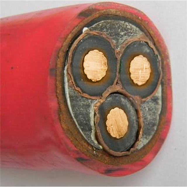


Product Description
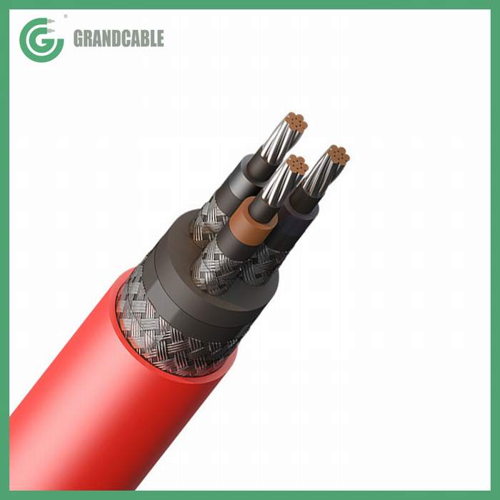
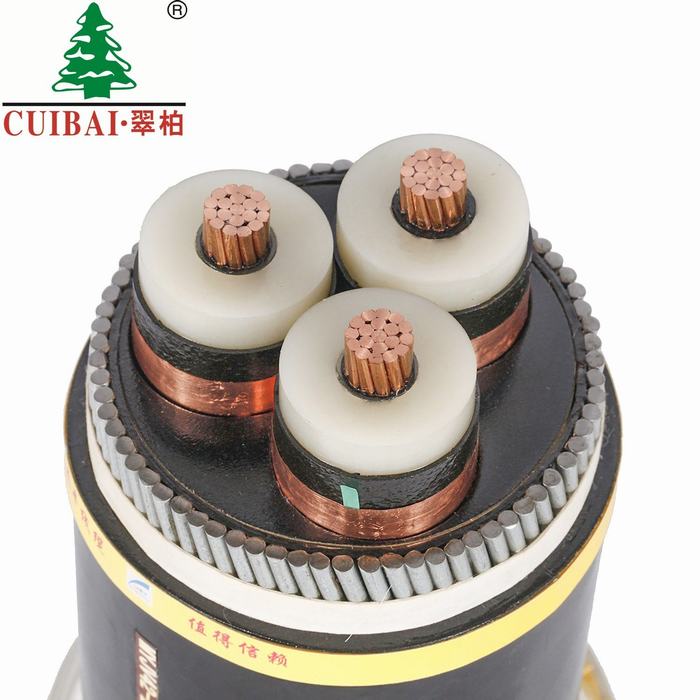
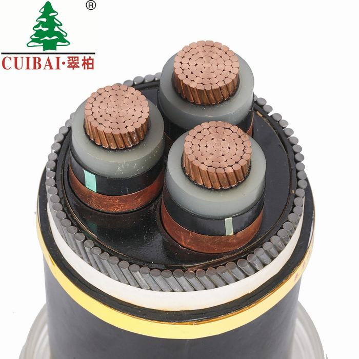
Medium Voltage Cable Three Core Cables to IEC 60502
APPLICATIONS
The three cores cables are designed for distribution of electrical power with nominal voltage Uo/U ranging from 1.8/3KV to 26/35KV and frequency 50Hz.
They are suitable for installation mostly in power supply stations, indoors and in cable ducts, outdoors, underground and in water as well as for installation on cable trays for industries, switchboards and power stations.
STANDARD
- IEC 60502 Part 1(1.8/3KV)
- IEC 60502 Part 2(3.6/6KV to 18/30KV)
| Conductor | Plain annealed copper or aluminium complying with IEC 60228 class 1 or 2. |
| Conductor Screen | The conductor screen consists of an extruded layer of non metallic, semi-conducting compound firmly bonded to the insulation to exclude all air voids. The conductor screen is not necessary for both PVC and EPR/HEPR insulated 1.8/3KV and 3.6/6KV cables. |
| Insulation | Insulation is of polyvinyl chloride (PVC) intended for 1.8/3KV and 3.6/6KV cables, cross-linked polyethylene compound (XLPE) or ethylene propylene rubber (EPR/HEPR). |
Table 1. Insulation Thickness of XLPE or EPR/HEPR Insulation
| Nom. Cross Section Area | Insulation Thickness at Nominal Voltage | |||||||||
|---|---|---|---|---|---|---|---|---|---|---|
| 1.8/3KV (Um=3.6KV) | 3.6/6KV (Um=7.2KV) | 6/10KV (Um=12KV) | 8.7/15KV (Um=17.5KV) | 12/20KV (Um=24KV) | 18/30KV (Um=36KV) | 21/35KV (Um=42KV) | 26/35KV (Um=42KV) | |||
| mm^2 | mm | mm | mm | mm | mm | mm | mm | mm | ||
| XLPE/EPR | XLPE | EPR | XLPE/EPR | XLPE/EPR | XLPE/EPR | XLPE/EPR | XLPE/EPR | XLPE/EPR | ||
| Unscreened | Screened | |||||||||
| 10 | 2.0 | 2.5 | 3.0 | 2.5 | – | – | – | – | – | – |
| 16 | 2.0 | 2.5 | 3.0 | 2.5 | 3.4 | – | – | – | – | – |
| 25 | 2.0 | 2.5 | 3.0 | 2.5 | 3.4 | 4.5 | – | – | – | – |
| 35 | 2.0 | 2.5 | 3.0 | 2.5 | 3.4 | 4.5 | 5.5 | – | – | – |
| 50 – 185 | 2.0 | 2.5 | 3.0 | 2.5 | 3.4 | 4.5 | 5.5 | 8.0 | 9.3 | 10.5 |
| 240 | 2.0 | 2.6 | 3.0 | 2.6 | 3.4 | 4.5 | 5.5 | 8.0 | 9.3 | 10.5 |
| 300 | 2.0 | 2.8 | 3.0 | 2.8 | 3.4 | 4.5 | 5.5 | 8.0 | 9.3 | 10.5 |
| 400 | 2.0 | 3.0 | 3.0 | 3.0 | 3.4 | 4.5 | 5.5 | 8.0 | 9.3 | 10.5 |
| 500 – 1600 | 2.2-2.8 | 3.2 | 3.2 | 3.2 | 3.4 | 4.5 | 5.5 | 8.0 | 9.3 | 10.5 |
*Insulation Thickness of PVC is 3.4mm (1- 1600mm sq) for 3.6/6KV cables.
| Insulaton Screen | The insulation screen consists of an extruded layer of non metallic, semiconducting compound extruded over the insulation. The extruded semi-conducting layer shall consist of bonded or cold strippable semi-conducting compound capable of removal for jointing or terminating. As an option, a semi-conducting tape may be applied over the extruded semi-conducting layer as a bedding for the metallic layer. The minimum thickness is 0.3 mm and the maximum resistivity is 500 Ohm-m at 90°C. The screen is tightly fitted to the insulation to exclude all air voids and can be easily hand stripped on site. The insulation screen is not necessary for both PVC and EPR/HEPR insulated 1.8/3KV and 3.6/6KV cables. The screen may be covered by semi-conductive water blocking swellable tape to ensure longitudinal watertightness. |
| Metallic Layer | The metallic layer may be applied over the individual cores or the core assembly collectively. |
The following types of metallic layers are provided:
1) Metallic Screen
2) Concentric Conductor
3) Metallic Sheath
4) Metallic armour
The metallic screen shall consist of either copper tapes or a concentric layer of copper wires or a combination of tapes and wires to provide an earth fault current path. The concentric conductor is applied directly either over the insulation, or over the insulation screen or over an inner covering. The metallic sheath consists of lead or lead alloy applied as a tightly fitting seamless tube. The metallic armour consists of either flat wire armour, round wire armour, and double tape armour.
Table 2. Minimum Total Cross Section of Metallic Screen
| Nom. Cross-Section Area of Cable | Min. Cross-Section of Metallic Screen | DC Resistance of the Copper Wire Screen |
|---|---|---|
| mm^2 | mm^2 | mm |
| up to 120 | 16 | 1.06 |
| 150-300 | 25 | 0.72 |
| 400-630 | 35 | 0.51 |
| 800-1000 | 50 | 0.35 |
| Separation Sheath (for armoured cable) | The separation sheath comprises a layer of extruded PVC, PE or LSZH, applied under the armour. The nominal thickness is calculated by 0.02Du + 0.6mm where Du is the fictitious diameter under the sheath in mm. For cables without a lead sheath, the nominal separation sheath thickness shall not be less than 1.2mm. For cables where the separation sheath is applied over the lead sheath, the nominal separation sheath thickness shall not be less than 1.0mm. |
| Lapped Bedding (for armoured lead sheathed cable) | The lapped bedding consists of either impregnated/synthetic compounded paper tapes or a combination of two layers of these paper tapes followed by a few layers of compounded fabulous materials. The thickness is around 1.5mm. |
| Armour (for armoured cable) | The armour consists of round aluminium wire armour applied helically over an extruded separation sheath. |
Table 3. Round Armour Wire Diameter
| Fictitious Diameter under the Armour | Armour Wire Diameter | |
|---|---|---|
| mm | mm | |
| > | < | |
| – | 10 | 0.8 |
| 10 | 15 | 1.25 |
| 15 | 25 | 1.6 |
| 25 | 35 | 2.0 |
| 35 | 60 | 2.5 |
| 60 | – | 3.15 |
| Over Sheath | Overall sheath comprises a layer of extruded thermoplastic compound (PVC, PE or LSZH can be offered as an option.) or elastomeric compound (polychlorprene CSP or chlorosulfonated PE). The nominal over sheath thickness is calculated by 0.035D+1 where D is the fictitiuous diameter immediately under the over sheath in mm. For unarmoured cables and cables with the over sheath not applied over the armour, metallic screen or concentric conductor, the nominal over sheath thickness shall not be less than 1.4mm. And for cables with over sheath applied over the armour, metallic screen or concentric conductor, the nominal over sheath thickness shall not be less than 1.8mm. |
PHYSICAL PROPERTIES
| Operating Temperature | up to 70°C (PVC insulation); up to 90°C (XLPE or EPR insulation) |
| Temperature Range | -5°C ( PVC or LSZH sheath ); -20°C ( PE sheath ) |
| Short Circuit Temperature( 5 seconds maximum duration ) | 140-160°C (PVC insulation) ; 250°C (XLPE or EPR insulation) |
| Bending Radius | 12 x OD |
Table 4. Nominal /Operating /Testing Voltages
| Rated Voltage Uo/U | Operating Voltage (Um) | Testing Voltage (rms) |
|---|---|---|
| 1.8/3KV | 3.6KV | 6.5KV |
| 3.6/6KV | 7.2KV | 12.5KV |
| 6/10KV | 12KV | 21KV |
| 8.7/15KV | 17.5KV | 30.5KV |
| 12/20KV | 24KV | 42KV |
| 18/30KV | 36KV | 63KV |
| 21/35KV | 42KV | 73.5(53)*KV |
| 26/35KV | 42KV | 91(65)*KV |
*21/35KV and 26/35KV power frequency voltage test can be made under the following conditions: 2.5Uo x 30mins or 3.0Uo x 15mins.
Numbers in brackets refer to the test values for 3.0Uo x 1.5mins.
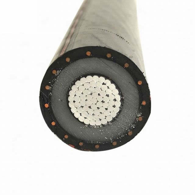
Single Core 1.8/3KV (Um=3.6KV)
- Next: 20kv Medium Voltage ABC Cables Electric Overhead Cable Wire
- Previous: Cable Tripolar De Aluminio Autoportante 8.7/15 Kv Na2xsa2y-S De 3X1X150mm2