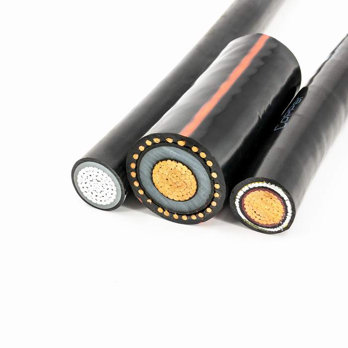
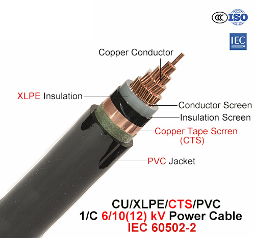
Cu/XLPE/Cts/PVC, Power Cable, 6/10 (12) Kv, 1/C (IEC 60502-2)


Product Description
The cable design conforms to IEC 60502 part 2. However if requested, we can separately offer guaranteed technical particulars for cables as per different international specifications or specific customer needs.
CONSTRUCTIONAL FEATURES
Conductor
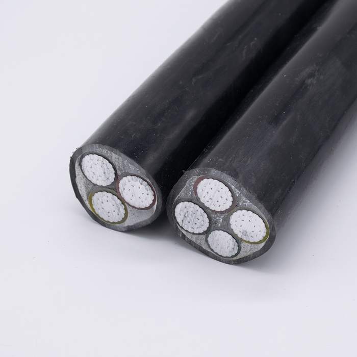
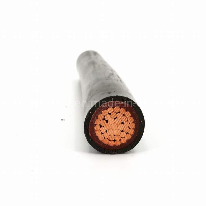
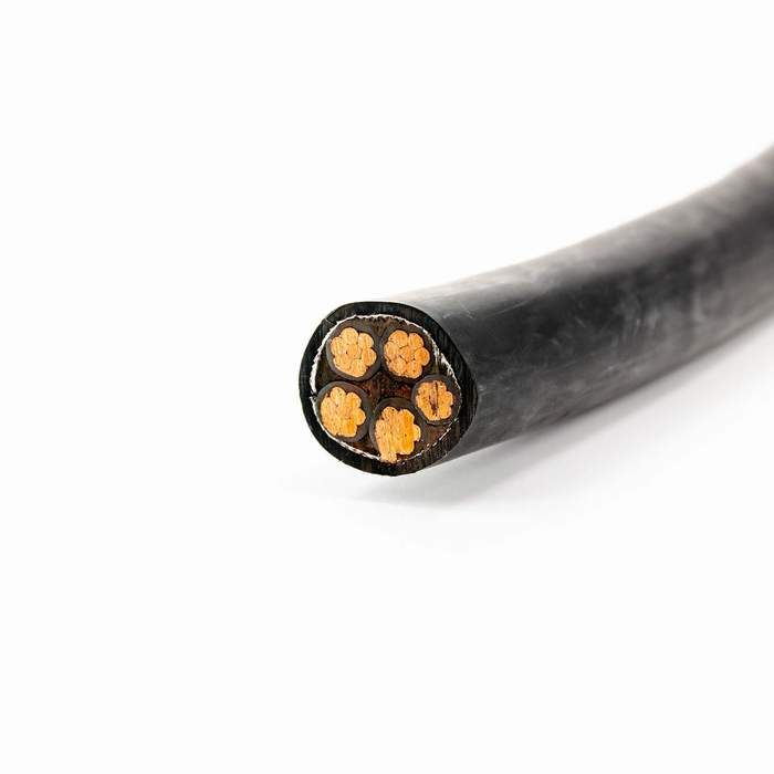
Copper Conductors upto 1000 sq mm will be circular compacted & stranded and shall comply with IEC-60228 Class 2.
Conductor screen
This will be an extruded layer of semiconducting XLPE applied under simultaneous triple extrusion process over the conductor along with the insulation and the insulation screen.
Insulation
This will be an extruded layer of insulating grade XLPE applied over conductor screen under triple extrusion process along with conductor screen and insulation screen.
Insulation screen
This will be a layer of semiconducting XLPE which will be applied by tripe extrusion process over the insulation.
Metallic screen
It will consist of a layer of copper tape applied helically with overlap over insulation screen. Other combinations of metallic screens as per customer’s requirement can also be provided on request.
Inner Sheath (Bedding)
Extruded layer of PVC or PE is applied over the laid-up cores. PVC is normally of grade ST2 or PE of grade ST7 as per IEC 60502 Part 2.
Outer sheath
An extruded layer is applied over the armour in case of armoured cables and over the laid up cores in case of unarmoured cables. Outer sheath material can be either PVC of grade ST2 or PE of grade ST7 as per IEC-60502 Part 2.
| Section | Conductor diameter | Conductor weight | Insulation thickness | Outer sheath thickness | Overall diameter | Cable weight | Minimum bending radius | Max. DC resistance of conductor at 20 °C |
| mm2 | mm | kg/km | mm | mm | mm | kg/km | mm | ohm/km |
| 25 | 5.9 | 218 | 3.4 | 1.8 | 19.5 | 575 | 390 | 0.727 |
| 35 | 6.9 | 303 | 3.4 | 1.8 | 20.5 | 685 | 410 | 0.524 |
| 50 | 8.1 | 408 | 3.4 | 1.8 | 22.0 | 825 | 440 | 0.387 |
| 70 | 9.7 | 591 | 3.4 | 1.8 | 23.5 | 1050 | 470 | 0.268 |
| 95 | 11.4 | 821 | 3.4 | 1.8 | 25.0 | 1325 | 500 | 0.193 |
| 120 | 12.9 | 1035 | 3.4 | 1.8 | 26.5 | 1580 | 530 | 0.153 |
| 150 | 14.3 | 1277 | 3.4 | 1.8 | 28.0 | 1855 | 560 | 0.124 |
| 185 | 16.0 | 1601 | 3.4 | 1.9 | 30.0 | 2240 | 600 | 0.0991 |
| 240 | 18.4 | 2105 | 3.4 | 2.0 | 32.5 | 2825 | 650 | 0.0754 |
| 300 | 20.6 | 2640 | 3.4 | 2.0 | 34.5 | 3420 | 690 | 0.0601 |
| 400 | 23.3 | 3383 | 3.4 | 2.1 | 38.0 | 4280 | 760 | 0.0470 |
| 500 | 26.3 | 4272 | 3.4 | 2.2 | 41.0 | 5275 | 820 | 0.0366 |
| 630 | 30.0 | 5618 | 3.4 | 2.3 | 45.0 | 6680 | 900 | 0.0283 |
| 800 | 34.2 | 7286 | 3.4 | 2.5 | 50.5 | 8445 | 1010 | 0.0221 |
| 1000 | 38.2 | 9046 | 3.4 | 2.6 | 54.5 | 10400 | 1090 | 0.0176 |
- Next: Cu/PVC/Cts/PVC, Control Cable, 0.6/1 Kv (IEC 60502-1)
- Previous: Fg7r/Fg7or, Rubber Cable, 0.6/1 Kv, Flexible Cu/Hepr/PVC (CEI 20-22/2)