
Copper Conductor Copper Clad Aluminum CCA Wire Stranded


Product Description
Applications
Solid and stranded (classes AA and A) bare copper are suitable for overhead transmission and distribution applications.
Stranded conductor of greater flexibility (classes B and C) are suitable for uninsulated hook up, jumpers, and grounds in electrical construction. Soft Drawn copper is unilay construction.
Specifications
B-1 Hard-Drawn Copper Wire.
B-2 Medium-Hard Copper Wire.
B-3 Soft or Annealed Copper Wire.
B-8 Concentric-Lay-Stranded Hard, Medium-Hard or Soft Copper Conductor.
B-33 Tinned Conductors
B-787 19 Wire Combination Unilay-Stranded Soft copper wire.
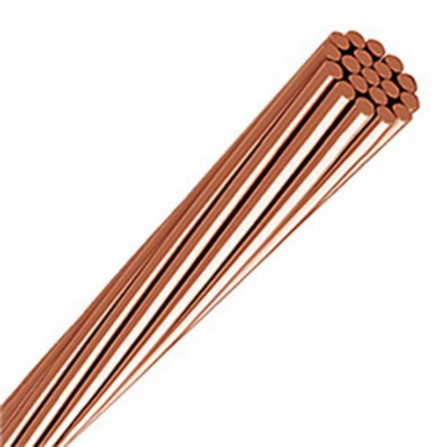
Construction
Bare copper, solid or stranded. Available in tempers hard, medium-hard, or soft. Stranded conductors are concentrically stranded in hard and medium-hard tempers and are Combination Unilay stranded in the soft-drawn temper.
| Size | Section | Number of Wires | Wire Diameter | Total Diameter | Resistance DC @ 20°C | Minimun Elongation in 10 In. Wire before Stranding (254 mm) | Total Weight | |
| AWG / MCM | Cmil | mm² | mm | mm | Ω/ km | % | kg / km | |
| 22 | 640 | 0.324 | 7 | 0.243 | 0.73 | 54.2 | 15 | 2.97 |
| 20 | 1,020 | 0.517 | 7 | 0.307 | 0.92 | 34.0 | 20 | 4.69 |
| 18 | 1,620 | 0.821 | 7 | 0.386 | 1.16 | 21.4 | 20 | 7.46 |
| 16 | 2,580 | 1.307 | 7 | 0.488 | 1.46 | 13.5 | 20 | 11.87 |
| 14 | 4,110 | 2.083 | 7 | 0.615 | 1.85 | 8.44 | 25 | 18.87 |
| 12 | 6,530 | 3.309 | 7 | 0.776 | 2.33 | 5.31 | 25 | 30.00 |
| 10 | 10,380 | 5.26 | 7 | 0.978 | 2.93 | 3.34 | 25 | 47.72 |
| 8 | 15,510 | 7.859 | 7 | 1.20 | 3.59 | 2.24 | 25 | 75.86 |
| 6 | 26,240 | 13.3 | 7 | 1.56 | 4.67 | 1.32 | 25 | 121 |
| 4 | 41,740 | 21.15 | 7 | 1.96 | 5.88 | 0.831 | 25 | 192 |
| 2 | 66,360 | 33.62 | 7 | 2.47 | 7.42 | 0.523 | 25 | 305 |
| 1 | 83,690 | 42.41 | 19 | 1.69 | 8.43 | 0.415 | 25 | 385 |
| 1/0 | 105,600 | 53.49 | 19 | 1.89 | 9.47 | 0.329 | 25 | 485 |
| 2/0 | 133,100 | 67.43 | 19 | 2.13 | 10.6 | 0.261 | 25 | 611 |
| 3/0 | 167,800 | 85.0 | 19 | 2.39 | 11.9 | 0.207 | 25 | 771 |
| 4/0 | 211,600 | 107.2 | 19 | 2.68 | 13.4 | 0.164 | 30 | 972 |
| 250 | 250,000 | 127 | 37 | 2.09 | 14.6 | 0.138 | 25 | 1,149 |
| 300 | 300,000 | 152 | 37 | 2.29 | 16.0 | 0.116 | 25 | 1,379 |
| 350 | 350,000 | 177 | 37 | 2.47 | 17.3 | 0.0994 | 25 | 1,609 |
| 400 | 400,000 | 203 | 37 | 2.64 | 18.5 | 0.0866 | 30 | 1,838 |
| 500 | 500,000 | 253 | 37 | 2.95 | 20.7 | 0.0695 | 30 | 2,298 |
| 600 | 600,000 | 304 | 61 | 2.52 | 22.7 | 0.0578 | 25 | 2,758 |
| 700 | 700,000 | 355 | 61 | 2.72 | 24.5 | 0.0495 | 30 | 3,216 |
| 750 | 750,000 | 380 | 61 | 2.82 | 25.3 | 0.0463 | 30 | 3,447 |
| 800 | 800,000 | 405 | 61 | 2.91 | 26.2 | 0.0434 | 30 | 3,676 |
| 900 | 900,000 | 456 | 61 | 3.09 | 27.8 | 0.0386 | 30 | 4,136 |
| 1,000 | 1,000,000 | 507 | 61 | 3.25 | 29.3 | 0.0347 | 30 | 4,596 |
HDBC, Stranded Bare Copper Conductor (AS 1746)
APPLICATIONS
Solid and stranded bare copper are suitable for overhead transmission and distribution applications.
Stranded conductor of greater flexibility are suitable for uninsulated hook up, jumpers, and grounds in electrical construction. Soft Drawn copper is unilay construction.
SPECIFICATIONS
AS 1746: Conductors-Bare overhead-Hard-drawn copper
CONSTRUCTION
Bare copper, solid or stranded. Available in tempers hard, medium-hard, or soft. Stranded conductors are concentrically stranded in hard and medium-hard tempers and are Combination Unilay stranded in the soft-drawn temper.
| Stranding and wire diameter | Approx. overall diameter | Cross-sectional area | Mass per | Calculated breaking laod (CBL) | Equivalent aluminium area | D.C. resistance per km at 20°C |
| mm | mm | mm2 | kg | kN | mm2 | Ω |
| 7/1.00 | 3.00 | 5.498 | 49.3 | 2.32 | 8.68 | 3.25 |
| 7/1.25 | 3.75 | 8.589 | 76.9 | 3.59 | 13.6 | 2.09 |
| 7/1.75 | 5.25 | 16.84 | 151 | 6.89 | 26.6 | 1.06 |
| 7/2.00 | 6.00 | 21.99 | 197 | 8.89 | 34.7 | 0.815 |
| 7/2.75 | 8.25 | 41.58 | 375 | 16.2 | 65.3 | 0.433 |
| 19/1.75 | 8.75 | 45.70 | 413 | 18.3 | 71.7 | 0.395 |
| 19/2.00 | 10.0 | 59.70 | 538 | 23.6 | 93.6 | 0.303 |
| 7/3.50 | 10.5 | 67.35 | 607 | 25.4 | 106 | 0.268 |
| 7/3.75 | 11.3 | 77.28 | 696 | 28.8 | 121 | 0.233 |
| 37/1.75 | 12.3 | 88.99 | 806 | 35.6 | 139 | 0.203 |
| 19/2.75 | 13.8 | 112.9 | 1020 | 43.1 | 177 | 0.160 |
| 19/3.00 | 15.0 | 134.3 | 1210 | 50.8 | 211 | 0.134 |
| 37/2.50 | 17.5 | 181.6 | 1640 | 70.3 | 284 | 0.099 6 |
| 37/2.75 | 19.3 | 219.8 | 1990 | 83.9 | 344 | 0.082 3 |
| 37/3.00 | 21.0 | 261.6 | 2370 | 98.9 | 409 | 0.069 1 |
| 61/2.75 | 24.8 | 362.3 | 3290 | 138.0 | 566 | 0.050 0 |
- Next: 5 Core Wire PVC Insulated Building Cable
- Previous: 2 Core Cable Flexible Rvv Cable 2X0.5mmsq Copper Cable Wire