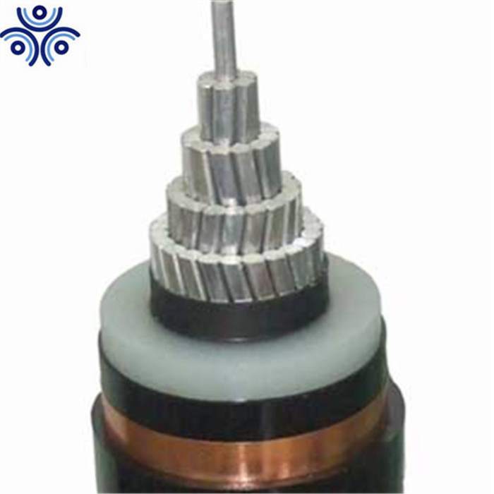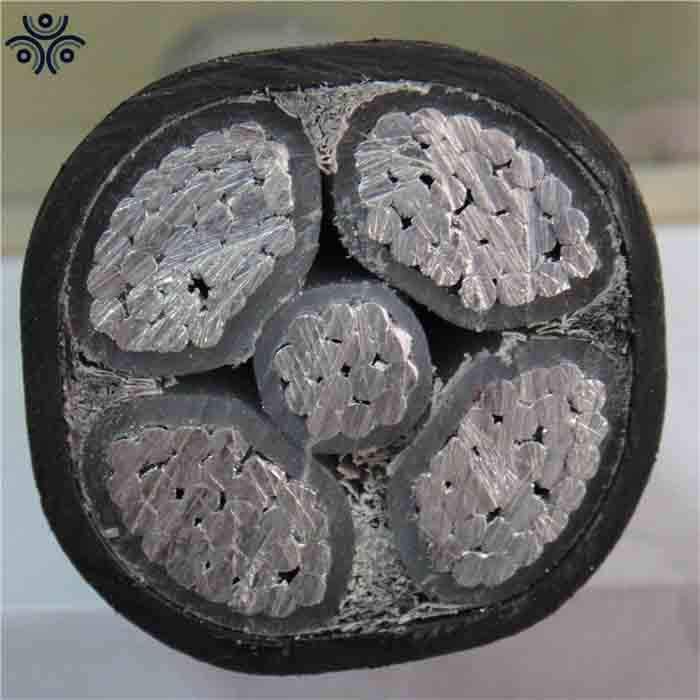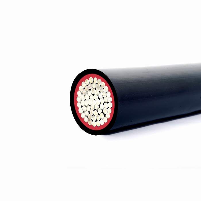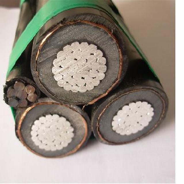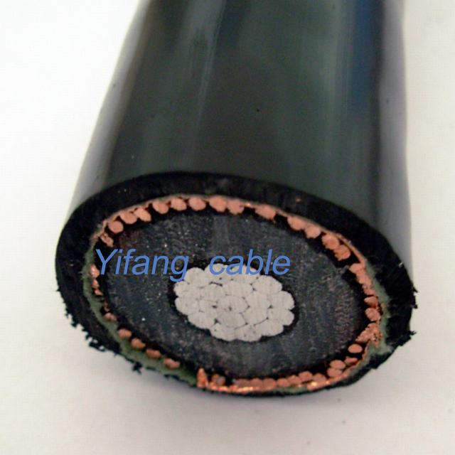
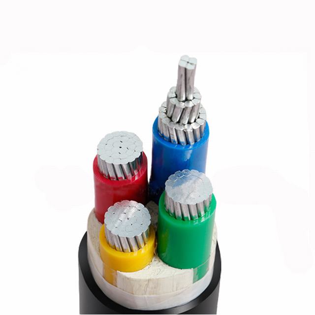
Aluminum XLPE Insulated PVC Insualted Sheated Power Cable


Product Description
Application
The power cable is used for fixed installations such as electric power distribution networks or industrial installations, which is laid in high fall area, able to bear external mechanical force, and certain pulling force.
Main technical data of 0.6/1KV, 4 core, Copper conductor, XLPE insulated and PVC or PE sheath cables CABLE
0.6/1KV CU/XLPE/PVC or PE
| Cable size | Conductor type | Nominal thickness of XLPE insulation(mm) | Nominal thickness of PVC or PE sheath(mm) | Approx. cable overall diameter (mm) | Max. D.C resistance @ 20 0 C (Ω/km) |
| 4×1.5mm 2 | RE or RM | 0.7 | 1.8 | 10.5 | 12.1 |
| 4×2.5mm 2 | RE or RM | 0.7 | 1.8 | 11.5 | 7.41 |
| 4x4mm 2 | RE or RM | 0.7 | 1.8 | 12.6 | 4.61 |
| 4x6mm 2 | RE or RM | 0.7 | 1.8 | 13.8 | 3.08 |
| 4x10mm 2 | RM | 0.7 | 1.8 | 16.9 | 1.83 |
| 4x16mm 2 | RM | 0.7 | 1.8 | 19.5 | 1.15 |
| 4x25mm 2 | SM | 0.9 | 1.8 | 21.3 | 0.727 |
| 4x35mm 2 | SM | 0.9 | 1.8 | 23.4 | 0.524 |
| 4x50mm 2 | SM | 1.0 | 1.9 | 26.8 | 0.387 |
| 4x70mm 2 | SM | 1.1 | 2.0 | 30.6 | 0.268 |
| 4x95mm 2 | SM | 1.1 | 2.1 | 34.9 | 0.193 |
| 4x120mm 2 | SM | 1.2 | 2.3 | 38.4 | 0.153 |
| 4x150mm 2 | SM | 1.4 | 2.4 | 42.5 | 0.124 |
| 4x185mm 2 | SM | 1.6 | 2.6 | 47.4 | 0.0991 |
| 4x240mm 2 | SM | 1.7 | 2.8 | 53.4 | 0.0754 |
| 4x300mm 2 | SM | 1.8 | 3.0 | 59.0 | 0.0601 |
Note: RE= round conductor RM = stranded conductor SM=sectional conductor
Parameter of 3+1 core power cable
|
Cable size |
Conductor type | Nominal thickness of XLPE insulation(mm) |
Nominal thickness of PVC or PE sheath(mm) |
Approx. cable overall diameter (mm) |
Max. D.C resistance @ 200C (Ω/km) |
|||
| Phase core | Earth core | Phase core | Earth core | Phase core | Earth core | |||
| 3×2.5+1.5mm2 | RE | RE | 0.7 | 0.7 | 1.8 | 11.2 | 7.41 | 12.1 |
| 3×4+2.5mm2 | RE | RE | 0.7 | 0.7 | 1.8 | 12.3 | 4.61 | 7.41 |
| 3×6+4mm2 | RE | RE | 0.7 | 0.7 | 1.8 | 13.5 | 3.08 | 4.61 |
| 3×10+6mm2 | RM | RE | 0.7 | 0.7 | 1.8 | 16.2 | 1.83 | 3.08 |
| 3×16+10mm2 | RM | RM | 0.7 | 0.7 | 1.8 | 18.8 | 1.15 | 1.83 |
| 3×25+16mm2 | SM | RM | 0.9 | 0.7 | 1.8 | 20.8 | 0.727 | 1.15 |
| 3×35+16mm2 | SM | RM | 0.9 | 0.7 | 1.8 | 22.4 | 0.524 | 1.15 |
| 3×50+25mm2 | SM | SM | 1.0 | 0.9 | 1.8 | 25.3 | 0.387 | 0.727 |
| 3×70+35mm2 | SM | SM | 1.1 | 0.9 | 1.9 | 28.9 | 0.268 | 0.524 |
| 3×95+50mm2 | SM | SM | 1.1 | 1.0 | 2.1 | 33.1 | 0.193 | 0.387 |
| 3×120+70mm2 | SM | SM | 1.2 | 1.1 | 2.2 | 36.6 | 0.153 | 0.268 |
| 3×150+70mm2 | SM | SM | 1.4 | 1.1 | 2.3 | 39.8 | 0.124 | 0.268 |
| 3×185+95mm2 | SM | SM | 1.6 | 1.1 | 2.5 | 44.7 | 0.0991 | 0.193 |
| 3×240+120mm2 | SM | SM | 1.7 | 1.2 | 2.7 | 50.1 | 0.0754 | 0.153 |
| 3×300+150mm2 | SM | SM | 1.8 | 1.4 | 2.9 | 55.4 | 0.0601 | 0.124 |
Note: RE= round conductor RM = stranded conductor SM=sectional conductor
- Next: Overhead Transmission Line ABC Aerial Bunched Cables
- Previous: Duplex AAAC Conductor Triplex ACSR Cable Price of ABC Aerial Bundle Cable
Contact us
Similar Or Related
-

N2xsy/Na2xsy Electric Single Core XLPE Insulated Copper Wire Shield 11kv Aluminum Power Cable
-
5 Core 70mm XLPE Insulated Aluminum/Copper Conductor Power Cable
-
Single Core Aluminum Conductor XLPE Insulation Power Cable Electrical Cable
-
11kv XLPE Insulated Aluminum Power Cable According to NFC 33-226 Standard
-