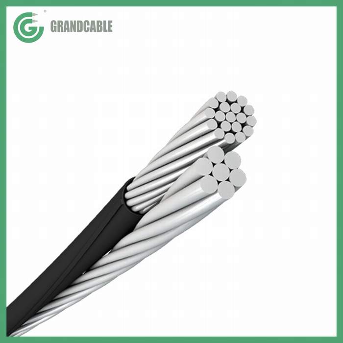
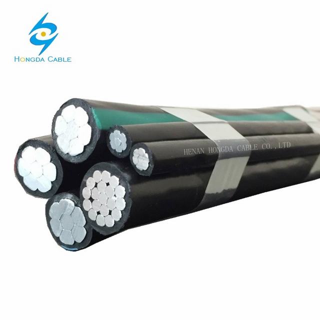
Aerial Bundled Cable Self-Supporting Insulated Wire SIP-2 3X35+1X50+2X25


Product Description
Wire (CIP) is a self-supporting insulated wire designed for use in overhead power lines (PTL) with suspension on supports or facades of buildings and structures.
Wire design (SIP):
1. A phase conductor of aluminum, stranded, sealed.
2. Zero bearing core made of aluminum alloy ABE or steel-aluminum, stranded, sealed. H. Insulation consists of light-stabilized polyethylene (XDPE).
Advantages of SIP:
~ with equivalent investments, power transmission lines with FIC require lower operating costs;
~ the possibility of joint suspension on the supports of wires with different voltage levels and with telephone lines;
~ reduction of safe distances to buildings and other engineering structures (electrical, telephone, overhead lines);
~ height above ground level – 4 meters, for uninsulated wires – 6 meters;
~ the possibility of a short circuit between the wires of the phases or to earth is excluded;
~ eliminating the risk of fire in the event of a wire falling to the ground;
~ high safety of service – no risk of damage due to contact of live phase wires;
~ lighter weight and longer duration of snow sticking, increased reliability in areas of intense icing, reduced wind loads on supports;
~ decrease in voltage drop due to low reactance;
~ reduction of emergency recovery work;
~ simplicity of repairs, especially when working under voltage, reducing the likelihood of electricity theft and destruction of power lines, safety of work near power lines.
1.3 Classification:
Low Voltage Cable Aerial Bundled Conductor, Twisted Cable
| Number of cores x nominal cross section | max. conductor- resistance | min. breaking load of conductor strand | Current rating in the air | Outer diameter | Total weight |
|---|---|---|---|---|---|
| mm^2 | Ohm/km | kN | A | mm | kg/km |
| 2×10 mm2 | 3.080 | 1.5 | 38 | 12.8 | 93 |
| 4×10 mm2 | 3.080 | 1.5 | 38 | 15.4 | 183 |
| 2×16 mm2 | 1.910 | 2.3 | 72 | 14.8 | 129 |
| 2×16+2×1.5 mm2 | 1.910/12.100 | 2.3 | 72 | 14.8 | 176 |
| 4×16 mm2 | 1.910 | 2.3 | 72 | 17.8 | 257 |
| 4×16+2×1.5 mm2 | 1.910/12.100 | 2.3 | 72 | 17.8 | 304 |
| 2×25 mm2 | 1.200 | 3.8 | 107 | 18.0 | 202 |
| 2×25+2×1,5 mm2 | 1.200/12.100 | 3.8 | 107 | 18.0 | 249 |
| 4×25 mm2 | 1.200 | 3.8 | 107 | 21.7 | 404 |
| 4×25+2×1,5 mm2 | 1.200/12.100 | 3.8 | 107 | 21.7 | 451 |
| 2×35 mm2 | 0.868 | 5.2 | 132 | 20.8 | 269 |
| 2×35+2×1,5 mm2 | 0.868/12.100 | 5.2 | 132 | 20.8 | 316 |
| 4×35 mm2 | 0.868 | 5.2 | 132 | 25.1 | 539 |
| 4×35+2×1,5 mm2 | 0.868/12.100 | 5.2 | 132 | 25.1 | 586 |
| 2×50 mm2 | 0.641 | 7.6 | 165 | 23.4 | 352 |
| 2×50+2×1,5 mm2 | 0.641/12.100 | 7.6 | 165 | 23.4 | 399 |
| 3×25+1×50 mm2 | 0.630/1.200 | 3.8 | 107 | 21.7 | 507 |
| 3×25+1×50+1×16 mm2 | 0.630/1.200/1.910 | 3.8/2.3 | 107/72 | 24.3 | 573 |
| 3×25+1×50+2×16 mm2 | 0.630/1.200/1.910 | 3.8/2.3 | 107/72 | 29.7 | 639 |
| 3×25+1×50+3×16 mm2 | 0.630/1.200/1.910 | 3.8/2.3 | 107/72 | 31.1 | 705 |
| 3×35+1×50 mm2 | 0.630/0.868 | 5.2 | 132 | 25.1 | 615 |
| 3×35+1×50+1×16 mm2 | 0.630/0.868/1.910 | 5.2/2.3 | 132/72 | 28.1 | 680 |
| 3×35+1×50+2×16 mm2 | 0.630/0.868/1.910 | 5.2/2.3 | 132/72 | 34.3 | 748 |
| 3×35+1×50+3×16 mm2 | 0.630/0.868/1.910 | 5.2/2.3 | 132/72 | 35.9 | 814 |
| 3×35+1×50+1×25 mm2 | 0.630/0.868/1.200 | 5.2/3.8 | 132/107 | 28.1 | 714 |
| 3×50+1×50 mm2 | 0.630/0.641 | 7.6 | 165 | 28.2 | 741 |
| 3×50+1×50+1×16 mm2 | 0.630/0.641/1.910 | 7.6/2.3 | 165/72 | 31.6 | 806 |
| 3×50+1×50+ 2×16 mm2 | 0.630/0.641/1.910 | 7.6/2.3 | 165/72 | 38.6 | 875 |
| 3×50+1×50+3×16 mm2 | 0.630/0.641/1.910 | 7.6/2.3 | 165/72 | 40.4 | 940 |
| 3×50+1×50+1×25 mm2 | 0.630/0.641/1.200 | 7.6/3.8 | 165/107 | 31.6 | 841 |
| 3×70+1×50 mm2 | 0.630/0.443 | 10.2 | 205 | 33.0 | 950 |
| 3×70+1×50+1×16 mm2 | 0.630/0.443/1.910 | 10.2/2.3 | 205/72 | 37.0 | 1014 |
| 3×70+1×50+2×16 mm2 | 0.630/0.443/1.910 | 10.2/2.3 | 205/72 | 45.2 | 1083 |
| 3×70+1×50+3×16 mm2 | 0.630/0.443/1.910 | 10.2/2.3 | 205/72 | 47.3 | 1148 |
| 3×70+1×50+1×25 mm2 | 0.630/0.443/1.200 | 10.2/3.8 | 205/107 | 37.0 | 1048 |
| 3×70+1×50+2×25 mm2 | 0.630/0.443/1.200 | 10.2/3.8 | 205/107 | 45.2 | 1150 |
| 3×70+1×50+3×25 mm2 | 0.630/0.443/1.200 | 10.2/3.8 | 205/107 | 47.3 | 1250 |
| 3×95+1×50 mm2 | 0.630/0.320 | 13.5 | 240 | 37.4 | 1176 |
| 3×95+1×50+1×16 mm2 | 0.630/0.320/1.910 | 13.5/2.3 | 240/72 | 41.9 | 1243 |
other cross-sections on request
| Physical Properties | ||||||||
| Cable size | Insulation Thickness | Approx Maximum Diameter | Approx. Net. Weight | Standard Length | ||||
| Phase | Neutral / Messenger | Public Lighting | Phase | Neutral/Messenger | Public Lighting | |||
| mm2 | mm | mm | mm | mm | mm | mm | kg/km | m |
| 2X25+25 | 1.4 | 1.4 | – | 10.0 | 10.0 | 10.0 | 338 | 500 |
| 2X35+25 | 1.6 | 1.4 | – | 11.2 | 10.0 | 10.0 | 394 | 500 |
| 2X50+35 | 1.6 | 1.6 | – | 12.6 | 11.2 | 11.2 | 526 | 500 |
| 2X70+50 | 1.8 | 1.6 | – | 15.4 | 12.6 | 12.6 | 760 | 500 |
| 2X95+70 | 2.0 | 1.8 | – | 17.0 | 15.4 | 15.4 | 975 | 500 |
| 3X25+25 | 1.4 | 1.4 | – | 10.0 | 10.0 | 10.0 | 452 | 500 |
| 3X35+25 | 1.6 | 1.4 | – | 11.2 | 10.0 | 10.0 | 537 | 500 |
| 3X50+35 | 1.6 | 1.6 | – | 12.6 | 11.2 | 11.2 | 717 | 500 |
| 3X70+50 | 1.8 | 1.6 | – | 15.4 | 12.6 | 12.6 | 1057 | 500 |
| 3X95+70 | 2.0 | 1.8 | – | 17.0 | 15.4 | 15.4 | 1360 | 500 |
| 3X25+25+2X16 | 1.4 | 1.4 | 1.2 | 10.0 | 10.0 | 8.1 | 602 | 500 |
| 3X35+25+2X16 | 1.6 | 1.4 | 1.2 | 11.2 | 10.0 | 8.1 | 687 | 500 |
| 3X50+35+2X16 | 1.6 | 1.6 | 1.2 | 12.6 | 11.2 | 8.1 | 867 | 500 |
| 3X70+50+2X16 | 1.8 | 1.6 | 1.2 | 15.4 | 12.6 | 8.1 | 1207 | 500 |
| 3X95+70+2X16 | 2.0 | 1.8 | 1.2 | 17.0 | 15.4 | 8.1 | 1510 | 500 |
| 3X25+25+16 | 1.4 | 1.4 | 1.2 | 10.0 | 10.0 | 8.1 | 527 | 500 |
| 3X35+25+16 | 1.6 | 1.4 | 1.2 | 11.2 | 10.0 | 8.1 | 612 | 500 |
| 3X50+35+16 | 1.6 | 1.6 | 1.2 | 12.6 | 11.2 | 8.1 | 792 | 500 |
| 3X70+50+16 | 1.8 | 1.6 | 1.2 | 15.4 | 12.6 | 8.1 | 1132 | 500 |
| 3X95+70+16 | 2.0 | 1.8 | 1.2 | 17.0 | 15.4 | 8.1 | 1435 | 500 |
For more information, don’t hesitate to contact us on +86-18339931106.
- Next: Cu XLPE Insulated Power Cable Yjy Zr-Yjy Wdzn-Yjy Cable 3*185+1*95
- Previous: 250mm2 Fire Resistant Rated Armoured & Un-Armoured Cwz Cable BS6387
Contact us
Similar Or Related
-

15kV 3 Core 4/0AWG Aluminum Conductor XLPE Insulated SWA Armored MV Power Cable
-
XLPE Insulated Aerial Service Drop Cable Conductor #3AWG Duplex ICEA S-66-524 NEMA WC7
-
3Cx185mm2 XLPE Insulated Copper Tape Screened Galvanized Steel Wire Armored Power Cable 33kV
-
0.6/1kV 4Cx500mm2 Copper Conductor PVC Insulated SWA Armored LV Power Cable IEC 60502-1
-
Low Voltage Single Core Power Cable 1X300 mm2 N2XCH CU/XLPE/CWS/LSF 0.6/1kV
-
Aerial Bundled Cable Self-Supporting Insulated Wire SIP-2 3X35+1X50+2X25