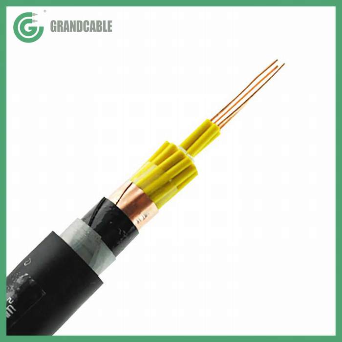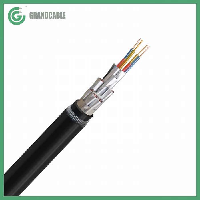
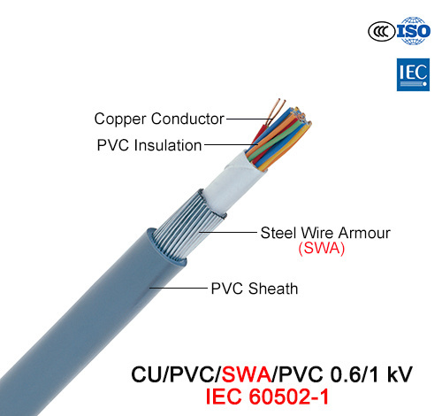
Cu/PVC/Swa/PVC, Control Cable, 0.6/1 Kv (IEC 60502-1)


Product Description
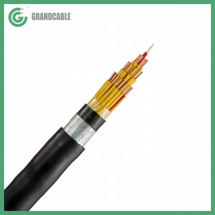
CONSTRUCTION:
Conductor: Plain annealed stranded circular copper conductor, as per Class 2 of IEC 60228.
Insulation: An extruded layer of Polyvinyl chloride (PVC) insulation, rated 70 º C at normal operation to IEC 60502-1.
Bedding: An extruded layer of Polyvinyl chloride (PVC).
Armour: Single layer of galvanized steel wires.
Outer Sheath: An extruded layer of Polyvinyl chloride (PVC) sheathing compound type ST1 to IEC 60502-1.
APPLICATION:
For use indoors in cable trenches or ducts; And outdoors – for connecting signaling and control units in industries, railways, traffic signals, power stations, industrial plants and switchgears if mechanical protection is not required, or in applications where the cable is not exposed to mechanical damage.
TECHNICAL DATA:
– Nominal voltage Uo/U = 0.6/1 kV
– Power frequency test voltage 3.5 kV for 5 minutes
– Max. Admissible temperature of conductor at normal operation 70 º C
– Max. Admissible temperature of conductor at short circuit 160 º C for 5 seconds
| Section | Max. Conductor Resistance | Current Rating | Overall Diameter | Cable Weight | |||
| DC at 20 | AC at 70 | Laid in Ground | Laid in Ducts | Laid in Free Air | |||
| No. x mm2 | Ω/km | Ω/km | A | A | A | mm | kg/km |
| 1.5 mm2 | |||||||
| 5 X 1.5 | 12.1000 | 14.6000 | 18.0 | 15.5 | 13.5 | 16.6 | 500 |
| 7 X 1.5 | 12.1000 | 14.6000 | 16.0 | 14.0 | 12.5 | 18.0 | 550 |
| 10 X 1.5 | 12.1000 | 14.6000 | 14.0 | 12.5 | 11.5 | 21.0 | 770 |
| 12 X 1.5 | 12.1000 | 14.6000 | 13.0 | 11.5 | 10.5 | 23.3 | 1080 |
| 14 X 1.5 | 12.1000 | 14.6000 | 12.0 | 10.5 | 9.5 | 24.2 | 1140 |
| 16 X 1.5 | 12.1000 | 14.6000 | 11.0 | 10.0 | 9.0 | 25.0 | 1260 |
| 19 X 1.5 | 12.1000 | 14.6000 | 10.0 | 9.0 | 8.0 | 26.0 | 1370 |
| 24 X 1.5 | 12.1000 | 14.6000 | 9.0 | 8.0 | 7.5 | 28.9 | 1620 |
| 30 X 1.5 | 12.1000 | 14.6000 | 8.0 | 7.5 | 6.5 | 31.0 | 1850 |
| 37 X 1.5 | 12.1000 | 14.6000 | 7.5 | 6.5 | 6.0 | 34.0 | 2250 |
| 2.5 mm2 | |||||||
| 5 X 2.5 | 7.4100 | 8.8700 | 24.0 | 20.5 | 18.0 | 17.8 | 600 |
| 7 X 2.5 | 7.4100 | 8.8700 | 22.0 | 18.5 | 16.0 | 19.2 | 660 |
| 10 X 2.5 | 7.4100 | 8.8700 | 20.0 | 16.5 | 14.5 | 23.8 | 960 |
| 12 X 2.5 | 7.4100 | 8.8700 | 18.0 | 15.5 | 13.5 | 25.0 | 1280 |
| 14 X 2.5 | 7.4100 | 8.8700 | 16.0 | 14.0 | 12.0 | 26.0 | 1390 |
| 16 X 2.5 | 7.4100 | 8.8700 | 15.0 | 13.0 | 11.0 | 27.0 | 1510 |
| 19 X 2.5 | 7.4100 | 8.8700 | 14.0 | 12.0 | 10.5 | 28.3 | 1670 |
| 24 X 2.5 | 7.4100 | 8.8700 | 13.0 | 11.0 | 9.5 | 31.4 | 2030 |
| 30 X 2.5 | 7.4100 | 8.8700 | 11.5 | 10.0 | 8.5 | 34.5 | 2450 |
| 37 X 2.5 | 7.4100 | 8.8700 | 10.0 | 9.0 | 7.5 | 37.4 | 2870 |
| 4.0 mm2 | |||||||
| 5 X 4.0 | 4.6100 | 5.5100 | 31.0 | 25.5 | 24.0 | 20.8 | 780 |
| 7 X 4.0 | 4.6100 | 5.5100 | 28.0 | 23.0 | 21.5 | 23.5 | 1190 |
| 10 X 4.0 | 4.6100 | 5.5100 | 25.0 | 21.0 | 19.5 | 27.2 | 1510 |
| 12 X 4.0 | 4.6100 | 5.5100 | 23.0 | 19.5 | 18.0 | 29.0 | 1700 |
| 14 X 4.0 | 4.6100 | 5.5100 | 20.5 | 17.0 | 16.0 | 30.0 | 1850 |
| 16 X 4.0 | 4.6100 | 5.5100 | 19.5 | 16.0 | 15.0 | 31.6 | 2040 |
| 19 X 4.0 | 4.6100 | 5.5100 | 18.0 | 15.0 | 14.0 | 33.0 | 2260 |
| 24 X 4.0 | 4.6100 | 5.5100 | 16.0 | 13.5 | 12.5 | 38.4 | 3070 |
| 30 X 4.0 | 4.6100 | 5.5100 | 14.5 | 12.0 | 11.0 | 41.3 | 3560 |
| 37 X 4.0 | 4.6100 | 5.5100 | 13.0 | 11.0 | 10.0 | 44.5 | 4120 |
- Next: Cu/XLPE/Swa/PVC, 0.6/1 Kv, Steel Wire Armored (SWA) Power Cable (BS 5467)
- Previous: E-Xay2y, Power Cable, 0.6/1 Kv, Al+Cu/PVC/PVC (HD 603)
Contact us
Similar Or Related
-

10X1.5mm2 Flame Retardant Copper Tape Screen Steel Tape Armored PVC Sheathed Control Cable 0.6/1kV
-
JZ-500 Flexible Copper Control Cable PVC Insulated 300/500V DIN VDE 0285-525
-
0.3/0.5kV 4X4mm2 Copper Wire Braiding PVC Insulation Low Voltage Control Power Cable
-
-
24X2.5mm2 XLPE Insulated Steel Tape Armoured Control/Instrumentation Cable IEC 60502-1
-